
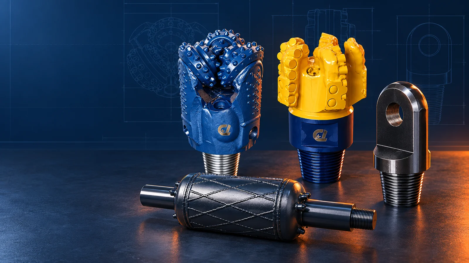
HDD tooling is the group of components that cuts the pilot bore, enlarges it and connects the drill string to the product during pullback. The main categories are pilot bits and heads, transmitter housings, drill pipe and drive components, adapters, reamers or hole openers, swivels, pulling eyes and replaceable wear parts.
Good selection treats these parts as one system. A strong reamer cannot compensate for an incompatible connection, inadequate fluid delivery or an underrated pullback component.
The three stages of an HDD tool string
1. Pilot drilling
The pilot assembly creates and steers the initial bore along the planned alignment. Depending on the ground and drilling system, the cutting tool may be a blade, carbide bit, PDC bit, tricone bit or other application-specific head.
The pilot assembly may also include:
- transmitter or sonde housing;
- fluid nozzles and passages;
- starter rod or adapter;
- retention hardware;
- wear protection and replaceable cutters.
The pilot tool must cut the formation while protecting steering accuracy and maintaining an open flow path for fluid and cuttings.
2. Bore enlargement
Many installations require the pilot hole to be enlarged before product pullback. The selected reamer or hole opener must create the planned diameter and transport the generated spoil.
Soil reamer categories include fly cutter, fluted, paddle, barrel/packer and multi-stage designs. Rock enlargement tools include PDC and roller-cone hole openers. The names vary by manufacturer; always review the actual cutting structure and intended formation.
3. Pullback
The pullback assembly connects the enlarged-hole tooling to the product. Depending on the engineered procedure, it can include:
- reamer or conditioning tool;
- swivel to isolate product rotation;
- shackles or rated connectors;
- pulling eye or pulling head;
- breakaway device where specified;
- adapters between verified connection standards.
Every component must be rated and inspected for the expected load. The lowest-rated component controls the assembly.
What the main components do
| Component | Main purpose | What to verify |
|---|---|---|
| Pilot bit/head | Cut and steer the pilot bore | Formation range, diameter, cutter type and housing compatibility |
| Transmitter housing | Carry the locating transmitter and transfer load | Sonde compatibility, signal, flow, connection and wear |
| Drill pipe | Transfer rotation, thrust/pullback and fluid | Rig compatibility, bend radius, thread condition and service limits |
| Adapter/sub | Join different verified interfaces | Thread standard, pin/box orientation, shoulder and rating |
| Reamer/hole opener | Enlarge and condition the bore | Formation, cutting action, pass diameter, fluid path and gauge |
| Swivel | Reduce transfer of tool rotation to the product | Load rating, rotation, sealing and connection |
| Pulling eye/head | Connect the product for pullback | Product fit, load path, fasteners and rated capacity |
| Wear parts | Protect or restore cutting and gauge surfaces | Material, placement, replacement criteria and inventory |
Tooling selection begins with six inputs
Ground conditions
Identify soil and rock by behavior, not color alone. Cohesive clay, unstable sand, cobble, fractured rock and competent rock demand different cutting and cleaning actions.
Bore geometry
Length, depth, entry/exit angles, curvature and minimum radius influence steering, connection length, cleaning and pullback load.
Product requirements
Record the product outside diameter, material, allowable pull load, minimum bend radius, pulling-head geometry and owner specification.
Drill capacity
Confirm drill-pipe size, connection, usable rotary torque, thrust/pullback, rotation speed and pump performance.
Fluid program
Fluid cools and lubricates tooling, stabilizes suitable formations and carries cuttings. The mixture and volume must match the ground, annulus and environmental plan.
Inspection and support
Choose tooling that can be inspected, serviced and supported within the project schedule. Confirm availability of cutters, nozzles, adapters, seals and drawings before mobilisation.
Connections: the detail that prevents many problems
HDD tooling can use API and manufacturer-specific interfaces. Similar-looking threads may not be interchangeable. Before makeup, verify:
- exact thread designation;
- pin or box orientation;
- shoulder condition;
- required torque and lubricant;
- adapter drawing and material;
- available breakout method.
Keep threads clean and protected during storage. Do not force a connection that does not make up smoothly and to the specified position.
A simple inspection routine
Before each run:
- clean the assembly;
- inspect cutters, cones, teeth and gauge surfaces;
- check nozzles and fluid passages;
- inspect welds, retainers and body condition;
- clean and inspect threads and shoulders;
- verify swivel rotation and pulling hardware;
- measure critical dimensions where required;
- record defects and replace parts outside service limits.
After each run, compare wear with the ground and operating data. Tool life has no universal interval; it changes with ground conditions, operation, steering and fluid practice.
Common selection mistakes
- choosing from diameter without confirming the formation;
- treating all rock or all soil as one condition;
- ignoring pump and cuttings-removal capacity;
- ordering an adapter from an unverified thread description;
- selecting a final reamer without planning the intermediate passes;
- continuing after loss of gauge, cutter damage or abnormal cone rotation;
- using unrated pullback hardware;
- failing to record actual performance for the next bore.
Frequently asked questions
What is the first HDD tool to select?
Start with the ground conditions, bore plan and drilling system. These inputs define the pilot cutting action and steering assembly. The reaming and pullback plan should then be designed around the as-drilled pilot and product requirements.
What is the difference between a bit and a reamer?
The bit creates the pilot bore. The reamer or hole opener enlarges that bore for the product and helps manage the generated spoil.
Why is a swivel used during pullback?
A correctly selected swivel allows the drill-side assembly to rotate while reducing rotation transferred to the product. It must be properly rated, connected and inspected.
How often should HDD tooling be inspected?
Inspect before and after every run and whenever operating data changes unexpectedly. Follow the manufacturer’s service criteria for individual components.
What information is needed for a complete tool recommendation?
Provide the ground profile, bore geometry, product details, drill model, pipe and connection, pump capacity, pilot and final diameters, planned passes and any previous tool-performance evidence.
References and further reading
- Plastic Pipe Institute: Mini-HDD guidance
- Vermeer: Getting more from HDD tooling
- Vermeer: Inspecting HDD tooling
Suggested internal CTA: Request a complete pilot, reaming and pullback tooling review for your next bore.